Dirk (Diskussion | Beiträge) K (→Library) |
Dirk (Diskussion | Beiträge) K (→Demos) |
||
| Zeile 799: | Zeile 799: | ||
===Demos=== | ===Demos=== | ||
====RP6v2 Base==== | ====RP6v2 Base==== | ||
| + | =====Config===== | ||
| + | =====Demo===== | ||
| + | |||
====RP6 CONTROL M32==== | ====RP6 CONTROL M32==== | ||
| + | =====Config===== | ||
| + | =====Demo===== | ||
==Phase 2== | ==Phase 2== | ||
Version vom 29. Mai 2012, 16:22 Uhr
Inhaltsverzeichnis
RP6v2 I2C-Portexpander: Hardware
In diesem Projekt soll eine "Exp" (RP6#Experimentierplatine, CONRAD 191537) für den RP6v2 (natürlich auch für den RP6) "gebaut" werden, auf der zuerst mit dem IC PCF8574 ein I2C-Portexpander realisiert werden soll. Mit den 8 neu gewonnenen I/O-Ports kann z.B. ein LC-Display betrieben werden. Für die Teile, die man für das ganze Projekt braucht, werden Bestell-Nummern vom großen C angegeben. Natürlich gibt es auch andere Versender, bei denen es evtl. günstiger wird.
Das Projekt wird in 2 Abschnitten ("Phasen") vorgestellt. Wer mitbauen will, kann auch schon nach der ersten Phase aussteigen, weil sie ohne die 2. Phase funktioniert.
So werden die 2 (3?) Phasen aussehen:
- Phase 1 -> Aufbau des PCF8574 (8 I/O-Ports) mit Wannenstecker für ein LCD
- Phase 2 -> Aufbau des PCF8591 (4 AD- und 1 DA-Wandler) mit Wannenstecker für die AD-/DA-Ports
- (Phase 3 -> Ich weiß nicht, ob es sie gibt. Aber: Ich hätte evtl. noch eine Idee dafür!)
Was braucht man allgemein für den Aufbau einer Schaltung auf der Exp:
- Seitenschneider, Schere, Zange
- Lötkolben 25..30 Watt, Lötzinn
- Plastik 70 Schutzlack (CONRAD 813621)
- Isolierter Schaltdraht YV 0,20 mm² (CONRAD 606065)
- Versilberter CU-Draht 0,6 mm (CONRAD 605581)
Mit dem versilberten CU-Draht stellt man auf der Unterseite (= Lötseite) der Exp Verbindungen zwischen den Bauteilen her; mit dem isolierten Schaltdraht werden Drahtbrücken auf der Oberseite (= Bestückungsseite) der Exp eingesetzt. Die Lage der Verbindungen zeige ich im Bestückungsplan jeder Phase. Man muss sich nicht an die genaue Lage der Verbindungen halten.
Wenn man die Drähte und Bauteile an anderen Positionen einlötet, kann es aber sein, dass man die nächste Phase nicht mehr so aufbauen kann, wie ich das hier zeige! Möglicherweise sind die weiteren Teile dann nur noch mit einer "wilden" Freiverdrahtung machbar!
Phase 1
In der Phase 1 wird das PHILIPS Portexpander-IC PCF8574AP oder PCF8574P mit seinen Verbindungen zu einem 14-poligen Wannenstecker als Anschluß für ein LCD aufgebaut. Alle RP6#Displays können hier direkt angeschlossen werden.
Man braucht folgende Bauteile (Bestell-Nummern CONRAD) für die 1. Phase:
| Anzahl | Bestell-Nr. | Bauteil-Bezeichnung: |
| 1 | 191537 | RP6 Experimentierplatine |
| 1 | Reichelt | IC PCF8574AP ODER |
| 1 | Reichelt | IC PCF8574P |
| 1 | 189626 | IC Sockel DIL 16-polig |
| 1 | 741687 | Wannenstecker gerade, 2 x 7-polig |
| 1 | 741119 | 1-reihige Stiftleiste RM 2,54mm (36-polig) |
| 1 | 742902 | Vier Codierbrücken (aus Set) |
| 1 | 430730 | Trimmpoti stehend 10kOhm (2,5 x 5mm) |
| 1 | 500812 | Keramik Kondensator 100 nF |
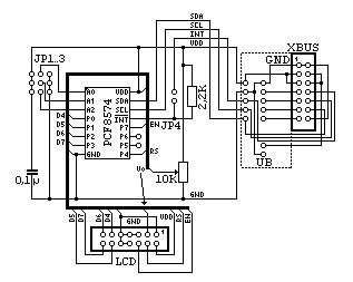
Hier erst einmal der Schaltplan:
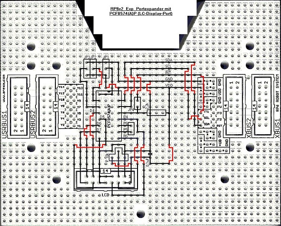
Und dann der Bestückungsplan:
Ich habe die Drahtbrücken aus isoliertem Schaltdraht (es sind 17) rot eingezeichnet. Sie werden auf der Oberseite der Experimentierplatine bestückt!
Viel Erfolg beim Aufbau!
Testen, ob die Schaltung grundsätzlich funktioniert, kann man mit der Demo "RP6Base_I2CMaster_01.c" aus den RP6v2 Examples. Die Demo zeigt ein Lauflicht, wenn man 8 LEDs an die Ausgangs-Ports des PCF8574 anschließt. Man sollte dazu low-current LEDs (z.B. rot 145998, grün 145971, gelb 145980) mit Vorwiderstand jeweils 1,5 kOhm (403270) an die Ausgänge anschließen,- Kathode an den Ausgang und Anode über Vorwiderstand an VDD. Die Ausgänge des PCF8574 sind zu finden an den Pins 4 (P4), 6 (P7), 11..14 (P0..P3) des LCD-Wannensteckers und an der 2-poligen Stiftleiste neben dem IC, beschriftet mit P5 P6. Auf die Jumper JP1..3 werden 3 Codierbrücken so aufgesteckt, dass die Adresseingänge des PCF8574 (A0..A2) mit GND verbunden sind (Position zum oberen Platinenrand). JP4 wird nicht aufgesteckt (INT nicht genutzt). Wenn der PCF8574AP eingesetzt wird, kann die I2C-Adresse im Demoprogramm "RP6Base_I2CMaster_01.c" unverändert bleiben. Wird jedoch der Typ PCF8574P verwendet, muss die I2C-Adresse geändert werden:
#define PCF8574_8LEDS_ADR 0x40
Später soll natürlich auch ein LCD angesteuert werden! Geduld ...
Phase 2
In der Phase 2 wird das PHILIPS Portexpander-IC PCF8591P mit seinen Verbindungen zu einem 10-poligen Wannenstecker als Anschluß für die AD- und DA-Ports aufgebaut.
Man braucht folgende Bauteile (Bestell-Nummern CONRAD) zusätzlich für die 2. Phase:
| Anzahl | Bestell-Nr. | Bauteil-Bezeichnung: |
| 1 | 152668 | IC PCF8591P |
| 1 | 189626 | IC Sockel DIL 16-polig |
| 1 | 741648 | Wannenstecker gerade, 2 x 5-polig |
| 1 | 460559 | Elektrolyt-Kondensator 10 uF/63 V |
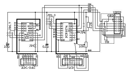
Hier erst einmal der Schaltplan:
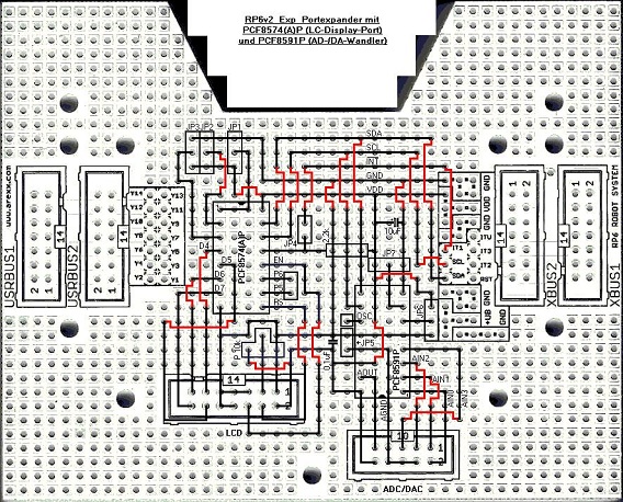
Und dann der Bestückungsplan:
Ich habe die Drahtbrücken aus isoliertem Schaltdraht (es sind ?) rot eingezeichnet. Sie werden auf der Oberseite der Experimentierplatine bestückt!
Viel Erfolg beim Aufbau!
Testen, ob die Schaltung grundsätzlich funktioniert, kann man mit der Demo "RP6Base_I2CMaster_02.c" aus den RP6v2 Examples. Die Demo zeigt das schon aus Phase 1 bekannte Lauflicht (mit dem PCF8574) und die 4 AD-Wandler Werte des PCF8591. Die angezeigten Werte werden zufällig sein, wenn an die analogen Eingangs-Ports des PCF8591 (AIN0..3) keine Schaltung angeschlossen ist. Man kann z.B. 4 LDRs zur Helligkeitsmessung verwenden. Als Vorbild kann man die Schaltung der Helligkeits-Sensoren des RP6v2 nehmen (Schaltplan RP6v2_SENSORS.pdf): Dort sind LDRs des Typs A9060 (145475) mit Widerständen 68 kOhm (403474) in Reihe geschaltet. Der ADC-Eingang liegt dann zwischen LDR und Widerstand. Die 4 Eingangs-Ports des PCF8591 findet man an den Pins 2, 1, 3, 5 (AIN0..3) des ADC/DAC-Wannensteckers. Auf die Jumper JP6, JP7 werden 2 Codierbrücken so aufgesteckt, dass die Adresseingänge des PCF8591 (A1..A2) mit GND verbunden sind (Position JP6 zum unteren, JP7 zum rechten Platinenrand). Auf JP5 wird ebenfalls eine Codierbrücke aufgesteckt (AGND = GND).
Der PCF8591 verfügt zusätzlich zu den 4 ADCs noch über einen DAC (Digital-Analog-Wandler). Dieser Ausgang (AOUT) ist verfügbar an Pin 9 des ADC/DAC-Wannensteckers. Nutzt man diese Funktion, kann man eine Spannung von 0..5 V an AOUT messen (JP5 aufgesteckt!).
Allgemeine Daten und Tabellen
Stecker
| Stecker | Pins | Bedeutung |
| P5 P6 | 2 | PCF8574: I/O-Ports P5, P6 |
| LCD | 14 | PCF8574: LCD-Wannenstecker (I/O-Ports P0..P3, P4, P7) |
| OSC | 1 | PCF8591: Oszillator Ein-/Ausgang |
| ADC/DAC | 10 | PCF8591: ADC/DAC-Wannenstecker (AIN0..AIN3, AOUT) |
LCD
| Pin | Port | LCD | Bedeutung |
| 1 | GND | VSS | |
| 2 | VDD | +5V | |
| 3 | Vo | Contrast | |
| 4 | P4 | RS | Data/Instruction |
| 5 | RW | = GND | |
| 6 | P7 | EN | Enable |
| 7 | D0 | = GND | |
| 8 | D1 | = GND | |
| 9 | D2 | = GND | |
| 10 | D3 | = GND | |
| 11 | P0 | D4 | Data LSB |
| 12 | P1 | D5 | Data |
| 13 | P2 | D6 | Data |
| 14 | P3 | D7 | Data MSB |
ADC/DAC
| Pin | Port | Bedeutung |
| 1 | AIN1 | Analogue Input 1 |
| 2 | AIN0 | Analogue Input 0 |
| 3 | AIN2 | Analogue Input 2 |
| 4 | AGND | Analogue Ground |
| 5 | AIN3 | Analogue Input 3 |
| 6 | AGND | Analogue Ground |
| 7 | AGND | Analogue Ground |
| 8 | AGND | Analogue Ground |
| 9 | AOUT | Analogue Output |
| 10 | VDD | +5V |
Jumper
Zeichenerklärung:
- Zweipolige Jumper:
- Stellung ON = Jumper aufgesteckt (Kontakt geschlossen)
- Stellung OFF = Jumper abgezogen (Kontakt offen)
- Dreipolige Jumper:
- Stellung O = Jumper oben * aufgesteckt
- Stellung U = Jumper unten * aufgesteckt
- Stellung L = Jumper links * aufgesteckt
- Stellung R = Jumper rechts * aufgesteckt
Zu *) Platine so gesehen, wie im Bestückungsplan!
| Jumper | Stellung | Bedeutung |
| JP1 | O (S) | PCF8574: A0 = 0 |
| JP1 | U | PCF8574: A0 = 1 |
| JP2 | O (S) | PCF8574: A1 = 0 |
| JP2 | U | PCF8574: A1 = 1 |
| JP3 | O (S) | PCF8574: A2 = 0 |
| JP3 | U | PCF8574: A2 = 1 |
| JP4 | ON | PCF8574: INT verwenden |
| JP4 | OFF (S) | PCF8574: INT nicht verwenden |
| JP5 | ON (S) | PCF8591: AGND = GND |
| JP5 | OFF | PCF8591: AGND variabel |
| JP6 | O | PCF8591: A1 = 1 |
| JP6 | U (S) | PCF8591: A1 = 0 |
| JP7 | L | PCF8591: A2 = 1 |
| JP7 | R (S) | PCF8591: A2 = 0 |
Zu (S) Standard-Stellung der Jumper!
I2C-Adressen
| A2 | A1 | A0 | PCF8574P | PCF8574AP | PCF8591P |
| 0 | 0 | 0 | 0x40 | 0x70 | 0x90 |
| 0 | 0 | 1 | 0x42 | 0x72 | nicht nutzbar * |
| 0 | 1 | 0 | 0x44 | 0x74 | 0x94 |
| 0 | 1 | 1 | 0x46 | 0x76 | nicht nutzbar * |
| 1 | 0 | 0 | 0x48 | 0x78 | 0x98 |
| 1 | 0 | 1 | 0x4A | 0x7A | nicht nutzbar * |
| 1 | 1 | 0 | 0x4C | 0x7C | 0x9C |
| 1 | 1 | 1 | 0x4E | 0x7E | nicht nutzbar * |
Zu *) Da A0 = 0 festgelegt!
RP6v2 I2C-Portexpander: Software
Phase 1
Library
Header
Datei RP6I2ClcdTWI.h:
/* ****************************************************************************
 *                           _______________________
 *                           \| RP6  ROBOT SYSTEM |/
 *                            \_-_-_-_-_-_-_-_-_-_/         		 >>> COMMON
 * ----------------------------------------------------------------------------
 * ------------------------ [c]2012 - Dirk ------------------------------------
 * ****************************************************************************
 * File: RP6I2ClcdTWI.h
 * Version: 1.0
 * Target: RP6 Base & Processor Expansion - ATMEGA32 @8.00 or 16.00MHz
 * Author(s): Dirk
 * ****************************************************************************
 * Description:
 * This is the RP6I2ClcdTWI header file.
 * You have to include this file, if you want to use the library
 * RP6I2ClcdTWI.c in your own projects.
 *
 * ****************************************************************************
 * THE CHANGELOG CAN BE FOUND AT THE END OF THIS FILE!
 * ****************************************************************************
 */

#ifndef RP6I2CLCDTWI_H
#define RP6I2CLCDTWI_H

/*****************************************************************************/
// Includes:

#include "RP6I2ClcdTWIConfig.h"		// Configure the target system

// Select includes depending on RP6I2ClcdTWIConfig.h:
#ifdef RP6BASE
	#include "RP6RobotBaseLib.h"	// The RP6 Robot Base Library.
#else
#ifdef RP6CONTROL
	#include "RP6ControlLib.h"		// The RP6 Control M32 Library.
#else
	#error DEFINE "RP6BASE" OR "RP6CONTROL" AS TARGET IN RP6I2ClcdTWIConfig.h
#endif
#endif
#include "RP6I2CmasterTWI.h"		// Include the I2C-Bus Master Library

/*****************************************************************************/
// Defines:

#ifndef HEX
	#define HEX 16
#endif
#ifndef DEC
	#define DEC 10
#endif
#ifndef OCT
	#define OCT 8
#endif
#ifndef BIN
	#define BIN 2
#endif

// Max. precision of the dtostre/dtostrf conversion:
#ifndef PRECISION
	#define PRECISION			6
#endif
// dtostre flags:
#ifndef DTOSTR_ALWAYS_SIGN
	#define DTOSTR_ALWAYS_SIGN	0x01	// ' ' for positive numbers
#endif
#ifndef DTOSTR_PLUS_SIGN
	#define DTOSTR_PLUS_SIGN	0x02	// '+' instead of ' '
#endif
#ifndef DTOSTR_UPPERCASE
	#define DTOSTR_UPPERCASE	0x04	// 'E' instead of 'e' for the exponent
#endif

/*****************************************************************************/
// I2C-LCD functions:

// A shadow register that simplifies the I2C to LCD communication:
typedef union {
	uint8_t byte;
	struct {
		unsigned LCDD : 4;
		unsigned RS   : 1;
		unsigned P5   : 1;
		unsigned P6   : 1;
		unsigned EN   : 1;
	};
} i2clcdPort_t;
extern i2clcdPort_t i2clcdPort;

void setI2CLCDD(uint8_t lcdd);
void write4BitI2CLCDData(uint8_t data);
void writeI2CLCDCommand(uint8_t cmd);
void initI2CLCD(void);

void clearI2CLCD(void);
void clearPosI2CLCD(uint8_t line, uint8_t pos, uint8_t length);

void writeCharI2CLCD(uint8_t ch);
void writeNStringI2CLCD_P(const char *pstring);
#define writeStringI2CLCD_P(__pstr) writeNStringI2CLCD_P((PSTR(__pstr)))
void writeStringI2CLCD(char *string);
void writeStringLengthI2CLCD(char *string, uint8_t length, uint8_t offset);

void _showScreenI2CLCD_P(const char *line1, const char *line2);
#define showScreenI2CLCD(__line1,__line2); ({_showScreenI2CLCD_P((PSTR(__line1)),(PSTR(__line2)));})

void writeIntegerI2CLCD(int16_t number, uint8_t base);
void writeIntegerLengthI2CLCD(int16_t number, uint8_t base, uint8_t length);
void writeLongI2CLCD(int32_t number, uint8_t base);
void writeLongLengthI2CLCD(int32_t number, uint8_t base, uint8_t length);
void writeDoubleI2CLCD(double number, uint8_t width, uint8_t prec);
void writeDoubleExpI2CLCD(double number, uint8_t prec, uint8_t flags);

void setCursorPosI2CLCD(uint8_t line, uint8_t pos);

#endif

/******************************************************************************
 * Additional info
 * ****************************************************************************
 * Changelog:
 *
 *  ---> changes are documented in the file "RP6I2ClcdTWI.c"
 *
 * ****************************************************************************
 */

/*****************************************************************************/
// EOF
Library
Datei RP6I2ClcdTWI.c:
/* ****************************************************************************
 *                           _______________________
 *                           \| RP6  ROBOT SYSTEM |/
 *                            \_-_-_-_-_-_-_-_-_-_/         		 >>> COMMON
 * ----------------------------------------------------------------------------
 * ------------------------ [c]2012 - Dirk ------------------------------------
 * ****************************************************************************
 * File: RP6I2ClcdTWI.c
 * Version: 1.0
 * Target: RP6 Base & Processor Expansion - ATMEGA32
 *         with LC-Display 16x2 chars (CONRAD 190911)
 *         [or Backlight Display 16x2 chars (CONRAD 191621)]
 *         connected to the RP6v2 I2C-Bus with a PHILIPS PCF8574
 *         I2C port expander.
 * Author(s): Dirk
 * ****************************************************************************
 * Description:
 * This is my RP6v2 I2C-LCD Library. It contains functions for driving an
 * LCD with an I2C port expander PCF8574 on the I2C-Bus. The PCF8574 may be
 * built up on an RP6v2 experiment board (CONRAD 191537) as shown here:
 *     ---> http://www.rn-wissen.de/index.php/RP6v2_I2C-Portexpander <---
 *
 * Connection of the LCD to the PCF8574:
 *  PCF8574   LCD
 *   P0..P3   D4..D7
 *   P4       RS
 *   P5, P6   n.c.
 *   P7       EN
 * LCD D0..D3 and LCD RW are connected to GND.
 * This pin allocation is compatible with "RN-Wissen", BASCOM-AVR AN-118
 * (lcd_i2c.lib) and "AsuroWiki: LCD Erweiterung".
 *
 * ****************************************************************************
 * THE CHANGELOG CAN BE FOUND AT THE END OF THIS FILE!
 * ****************************************************************************
 */

/*****************************************************************************/
// Includes:

#include "RP6I2ClcdTWI.h"

/*****************************************************************************/
// I2C-LCD functions:

// All I2C-LCD routines are prepared to control a 2x16 character LCD.
// If you want to connect a bigger LCD you need to change some things in
// these routines! (especially in the initI2CLCD, setCursorI2CLCD and
// showScreenI2CLCD routines)

// A shadow register for the I2C to LCD communication:
i2clcdPort_t i2clcdPort;

char lcd_tmp_buffer[17];

/**
 * Sets new 4-bit data for the LCD and also pulses the enable line of the
 * LCD to 'inform' the LCD about the new data.
 */
void setI2CLCDD(uint8_t lcdd)
{
	i2clcdPort.LCDD = lcdd;
	i2clcdPort.EN = 1;
	I2CTWI_transmitByte(PCF8574_LCD_ADR, i2clcdPort.byte);
	delayCycles(50);
	i2clcdPort.EN = 0;
	I2CTWI_transmitByte(PCF8574_LCD_ADR, i2clcdPort.byte);
}

/**
 * Write a 8bit-byte in two nibbles of 4bit to the LCD.
 */
void write4BitI2CLCDData(uint8_t data)
{
	setI2CLCDD(data >> 4);
	setI2CLCDD(data);
	delayCycles(150);
}

/**
 * Write a command to the LCD.
 */
void writeI2CLCDCommand(uint8_t cmd)
{
	i2clcdPort.RS = 0;
	write4BitI2CLCDData(cmd);
	delayCycles(150);
}

/**
 * Initialize the LCD. Always call this before using the I2C-LCD!
 *
 */
void initI2CLCD(void)
{
	//delayCycles(34000); No need for Power ON delay as usually the
	// Bootloader should have been executed before...
	setI2CLCDD(0b0011);
	delayCycles(18000);
	setI2CLCDD(0b0011);
	delayCycles(5500);
	setI2CLCDD(0b0011);
	delayCycles(5500);
	setI2CLCDD(0b0010);
	delayCycles(5500);
	writeI2CLCDCommand(0b00101000);
	delayCycles(5500);
	writeI2CLCDCommand(0b00001000);
	delayCycles(5500);
	writeI2CLCDCommand(0b00000001);
	delayCycles(5500);
	writeI2CLCDCommand(0b00000010);
	delayCycles(5500);
	writeI2CLCDCommand(0b00001100);
	delayCycles(5500);
}

/**
 * Clears the whole LCD!
 */
void clearI2CLCD(void)
{
	writeI2CLCDCommand(0b00000001);
	delayCycles(5500);
}

/**
 * Clears some characters after the given position.
 */
void clearPosI2CLCD(uint8_t line, uint8_t pos, uint8_t length)
{
	setCursorPosI2CLCD(line, pos);
	while(length--)
		writeCharI2CLCD(' ');
}

/**
 * Write a single character to the LCD.
 *
 * Example:
 *
 *			writeCharI2CLCD('R');
 *			writeCharI2CLCD('P');
 *			writeCharI2CLCD('6');
 *			writeCharI2CLCD(' ');
 *			writeCharI2CLCD('0');
 *			writeCharI2CLCD(48); // 48 is ASCII code for '0'
 *			writeCharI2CLCD(49); // '1'
 *			writeCharI2CLCD(50); // '2'
 *			writeCharI2CLCD(51); // '3'
 *			//...
 *
 *			would output:
 *			RP6 00123
 *			at the current cursor position!
 *			use setCursorPosI2CLCD function to move the cursor to a
 *			different location!
 */
void writeCharI2CLCD(uint8_t ch)
{
	i2clcdPort.RS = 1;
	write4BitI2CLCDData(ch);
	delayCycles(50);
}

/**
 * Writes a null terminated string from flash program memory to the LCD.
 * You can use the macro writeStringI2CLCD_P(STRING); instead, this macro
 * ensures that the String is stored in program memory only!
 *
 * Example:
 *
 *			writeNStringI2CLCD_P(PSTR("RP6 Control"));
 *
 *			// There is also a Macro that makes life easier and
 *			// you can simply write:
 *			writeStringI2CLCD_P("RP6 Control");
 *
 */
void writeNStringI2CLCD_P(const char *pstring)
{
    uint8_t c;
    for (; (c = pgm_read_byte_near(pstring++)); writeCharI2CLCD(c));
}

/**
 * Writes a String from SRAM to the LCD.
 */
void writeStringI2CLCD(char *string)
{
	while(*string)
		writeCharI2CLCD(*string++);
}

/**
 * Writes a string with specified length and offset from SRAM to the LCD.
 * If it is a null terminated string, output will be stopped at the
 * end. It does not need to be null terminated, but it is recommended
 * to use only null terminated strings/buffers, otherwise the function could
 * output any SRAM memory data stored after the string until it reaches a 0
 * or the specified length!
 *
 * Example:
 *
 *			writeStringLengthI2CLCD("RP6 Robot Sytem",16,0);
 *			// would output: "RP6 Robot Sytem\n"
 *			writeStringLengthI2CLCD("RP6 Robot Sytem",11,4);
 *			// would output: "Robot System"
 * 			writeStringLengthI2CLCD("RP6 Robot Sytem",40,4);
 *			// would output: "Robot System"
 *			// No matter if the specified length is 40 characters!
 *
 */
void writeStringLengthI2CLCD(char *string, uint8_t length, uint8_t offset)
{
	for(string = &string[offset]; *string && length; length--)
		writeCharI2CLCD(*string++);
}

/**
 * This function is useful for displaying text screens on the LCD.
 * It clears the whole LCD and writes the two Strings to line 1 and
 * line 2.
 */
void _showScreenI2CLCD_P(const char *line1, const char *line2)
{
	clearI2CLCD();
	writeNStringI2CLCD_P(line1);
	setCursorPosI2CLCD(1, 0);
	writeNStringI2CLCD_P(line2);
}

/**
 * Write a number (with specified base) to the LCD.
 *
 * Example:
 *
 *			// Write a hexadecimal number to the LCD:
 *			writeIntegerI2CLCD(0xAACC,16);
 *			// Instead of 16 you can also write "HEX" as this is defined in the
 *			// RP6I2ClcdTWI.h :
 *			writeIntegerI2CLCD(0xAACC, HEX);
 *			// Other Formats:
 *			writeIntegerI2CLCD(1024,DEC);  	// Decimal
 *			writeIntegerI2CLCD(511,OCT);		// Ocal
 *			writeIntegerI2CLCD(0b11010111,BIN); // Binary
 */
void writeIntegerI2CLCD(int16_t number, uint8_t base)
{
	itoa(number, &lcd_tmp_buffer[0], base);
	writeStringI2CLCD(&lcd_tmp_buffer[0]);
}

/**
 * Same as writeIntegerI2CLCD, but with defined length.
 * This means this routine will add leading zeros to the number if length is
 * larger than the actual value or cut the upper digits if length is smaller
 * than the actual value.
 *
 * Example:
 *
 *			// Write a hexadecimal number to the LCD:
 *			writeIntegerLengthI2CLCD(0xAACC, 16, 8);
 *			// Instead of 16 you can also write "HEX" as this is defined in the
 *			// RP6I2ClcdTWI.h :
 *			writeIntegerLengthI2CLCD(0xAACC, HEX, 8);
 *			// Other Formats:
 *			writeIntegerLengthI2CLCD(1024,DEC,6);  	// Decimal
 *			writeIntegerLengthI2CLCD(511,OCT,4);		// Ocal
 *			writeIntegerLengthI2CLCD(0b11010111,BIN,8); // Binary
 */
void writeIntegerLengthI2CLCD(int16_t number, uint8_t base, uint8_t length)
{
	char buffer[17];
	itoa(number, &buffer[0], base);
	int8_t cnt = length - strlen(buffer);
	if(cnt > 0) {
		for(; cnt > 0; cnt--, writeCharI2CLCD('0'));
		writeStringI2CLCD(&buffer[0]);
	}
	else
		writeStringLengthI2CLCD(&buffer[0], length, -cnt);
}

/**
 * Write a long number (with specified base) to the LCD.
 *
 * Example:
 *
 *			// Write a hexadecimal number to the LCD:
 *			writeLongI2CLCD(0xAACC,16);
 *			// Instead of 16 you can also write "HEX" as this is defined in the
 *			// RP6I2ClcdTWI.h :
 *			writeLongI2CLCD(0xAACC, HEX);
 *			// Other Formats:
 *			writeLongI2CLCD(1024,DEC);  	// Decimal
 *			writeLongI2CLCD(511,OCT);		// Octal
 *			writeLongI2CLCD(0b11010111,BIN); // Binary
 */
void writeLongI2CLCD(int32_t number, uint8_t base)
{char buffer[33];
	ltoa(number, &buffer[0], base);
	writeStringI2CLCD(&buffer[0]);
}

/**
 * Same as writeLongLCD, but with defined length.
 * This means this routine will add leading zeros to the number if length is
 * larger than the actual value or cut the upper digits if length is smaller
 * than the actual value.
 *
 * Example:
 *
 *			// Write a hexadecimal number to the LCD:
 *			writeLongLengthI2CLCD(0xAACC, 16, 8);
 *			// Instead of 16 you can also write "HEX" as this is defined in the
 *			// RP6I2ClcdTWI.h :
 *			writeLongLengthI2CLCD(0xAACC, HEX, 8);
 *			// Other Formats:
 *			writeLongLengthI2CLCD(1024,DEC,6);		// Decimal
 *			writeLongLengthI2CLCD(511,OCT,4);		// Octal
 *			writeLongLengthI2CLCD(0b11010111,BIN,8); // Binary
 */
void writeLongLengthI2CLCD(int32_t number, uint8_t base, uint8_t length)
{char buffer[33];
	ltoa(number, &buffer[0], base);
	int8_t cnt = length - strlen(buffer);
	if(cnt > 0) {
		for(; cnt > 0; cnt--, writeCharI2CLCD('0'));
		writeStringI2CLCD(&buffer[0]);
	}
	else
		writeStringLengthI2CLCD(&buffer[0], length, -cnt);
}

/**
 * Write a floating point number to the LCD.
 *
 * Example:
 *
 *			// Write a floating point number to the LCD (no exponent):
 *			writeDoubleI2CLCD(1234567.890, 11, 3);
 *
 * The value of prec (precision) defines the number of decimal places.
 * For 32 bit floating point variables (float, double ...) 6 is
 * the max. value for prec (7 relevant digits).
 * The value of width defines the overall number of characters in the
 * floating point number including the decimal point. The number of
 * pre-decimal positions is: (width - prec - 1).
 */
void writeDoubleI2CLCD(double number, uint8_t width, uint8_t prec)
{char buffer[width + 1];
	dtostrf(number, width, prec, &buffer[0]);
	writeStringI2CLCD(&buffer[0]);
}

/**
 * Write a floating point number to the LCD.
 *
 * Example:
 *
 *			// Write a floating point number to the LCD (with exponent):
 *			writeDoubleExpI2CLCD(-123.456, 3, 0);
 *			// ... if you want a '+' sign for positive numbers:
 *			writeDoubleExpI2CLCD(+123.456, 3, DTOSTR_PLUS_SIGN);
 *
 * The value of prec (precision) defines the number of decimal places.
 * For 32 bit floating point variables (float, double ...) 6 is
 * the max. value for prec (7 relevant digits).
 */
void writeDoubleExpI2CLCD(double number, uint8_t prec, uint8_t flags)
{char buffer[prec + 8];
	dtostre(number, &buffer[0], prec, flags);
	writeStringI2CLCD(&buffer[0]);
}

/**
 * Sets the cursor position on LCD.
 */
void setCursorPosI2CLCD(uint8_t line, uint8_t pos)
{
	pos |= 128;
	if(line == 1) pos += 0x40;
	writeI2CLCDCommand(pos);
}

/******************************************************************************
 * Additional info
 * ****************************************************************************
 * Changelog:
 * - v. 1.0 (initial release) 28.05.2012 by Dirk
 *
 * ****************************************************************************
 */

/*****************************************************************************/
// EOF
Demos
RP6v2 Base
Config
Demo
RP6 CONTROL M32
Config
Demo
Phase 2
Siehe auch
Quellen
Autoren
--Dirk 20:13, 26. Mai 2012 (CET)


