Aus RN-Wissen.de

Diese Spezialseite listet alle hochgeladenen Dateien auf.
Erste Seite |
Vorherige Seite |
Nächste Seite |
Letzte Seite |
| Datum | Name | Vorschaubild | Größe | Beschreibung | Versionen |
|---|---|---|---|---|---|
| 14:26, 31. Okt. 2014 | 2014 07 05 vergleich 555 556.JPG (Datei) | 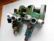 |
240 KB | 1 | |
| 14:25, 31. Okt. 2014 | 2014 07 05 bake 556.JPG (Datei) | 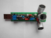 |
250 KB | 1 | |
| 15:05, 15. Mai 2014 | Testaufbau blinker.JPG (Datei) | 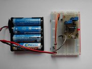 |
191 KB | Testaufbau Blinker | 1 |
| 10:02, 15. Mai 2014 | IR-bake mit blinkerplatine.JPG (Datei) | 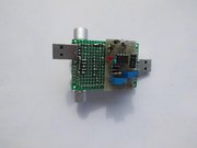 |
114 KB | IR-bake kpl. mit Blinkerplatine | 1 |
| 10:02, 15. Mai 2014 | IR-bake bauteilseite mit reflektoren.JPG (Datei) | 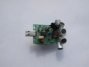 |
107 KB | IR-bake kpl. mit Reflektoren | 1 |
| 09:59, 15. Mai 2014 | Abschirmung IR empfaenger RP6.JPG (Datei) | 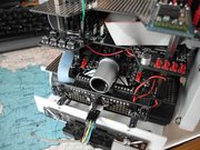 |
222 KB | RP6 mit Abschirmung am IR-Empfänger | 1 |
| 09:58, 15. Mai 2014 | Abschirmung IR empfaenger-2.JPG (Datei) | 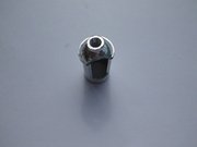 |
76 KB | Abschirmung IR-Empfänger Draufsicht | 1 |
| 09:57, 15. Mai 2014 | Abschirmung IR empfaenger-1.JPG (Datei) | 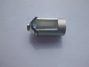 |
82 KB | Abschirmung IR-Empfänger Seitenansicht | 1 |
| 09:56, 15. Mai 2014 | Reflektor IR diode.JPG (Datei) |  |
93 KB | Reflektor für IR-Senderdiode | 1 |
| 09:54, 15. Mai 2014 | 2014 05 04 sender blinker mit litzen verbunden.JPG (Datei) | 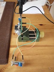 |
217 KB | Messaufbau mit Litzen zwischen IR-Sender und Blinker | 1 |
| 09:53, 15. Mai 2014 | 2014 05 04 RP6 an messstrecke.JPG (Datei) | 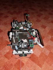 |
193 KB | RP6 Messaufbau 5m Entfernung | 1 |
| 09:51, 15. Mai 2014 | 2014 05 04 bake an messstrecke.JPG (Datei) | 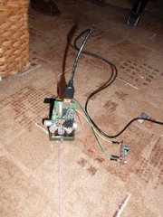 |
190 KB | IR-bake Messaufbau 5m Entfernung | 1 |
| 09:49, 15. Mai 2014 | 2014 05 04 terminal IR-bake 1.jpg (Datei) | 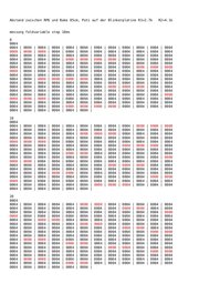 |
275 KB | Ausgabe IR-bake Software case2 | 1 |
| 09:46, 15. Mai 2014 | Ir bake kpl hochkant.jpg (Datei) | 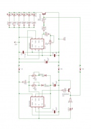 |
82 KB | Stromlaufplan IR-bake kpl. | 1 |
| 09:45, 15. Mai 2014 | IR bake blinker blatt 1.jpg (Datei) | 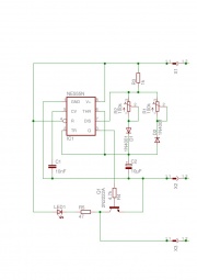 |
48 KB | Stromlaufplan IR-bake Blinker | 1 |
| 09:44, 15. Mai 2014 | Sender und blinker steckposition.jpg (Datei) | 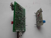 |
189 KB | IR-Sender und Blinker in Steckposition | 1 |
| 09:42, 15. Mai 2014 | Blinker loetseite-1.JPG (Datei) | 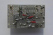 |
65 KB | Blinker Lötseite | 1 |
| 09:42, 15. Mai 2014 | Blinker bauteilseite-1.JPG (Datei) | 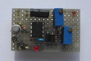 |
203 KB | Blinker Bauteilseite | 1 |
| 09:39, 15. Mai 2014 | Anschluss hameg.JPG (Datei) | 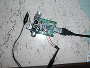 |
217 KB | Anschluss des IR-Senders | 1 |
| 09:38, 15. Mai 2014 | Einstellungen HAMEG.JPG (Datei) | 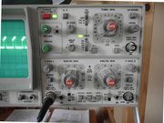 |
248 KB | Einstellungen am Oszilloskop | 1 |
| 09:37, 15. Mai 2014 | Aufnahme 7DIV 5per.JPG (Datei) | 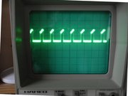 |
214 KB | 36kHz des IR-Senders auf dem Oszilloskop | 1 |
| 09:34, 15. Mai 2014 | Testplatz IR-Bake.JPG (Datei) | 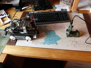 |
176 KB | Testaufbau IR-bake | 1 |
| 09:32, 15. Mai 2014 | IR bake sender blatt 2.jpg (Datei) | 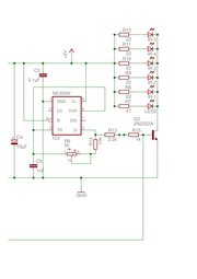 |
56 KB | Stromlaufplan IR-bake Sender | 1 |
| 09:31, 15. Mai 2014 | IR-bake mit netzteil kpl stehend.JPG (Datei) | 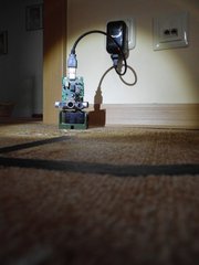 |
155 KB | IR-bake kpl. im Halter stehend | 1 |
| 09:30, 15. Mai 2014 | IR-bake mit netzteil kpl haengend.JPG (Datei) |  |
135 KB | IR-bake kpl. am Kabel hängend | 1 |
| 09:28, 15. Mai 2014 | IR bake sender oben.JPG (Datei) | 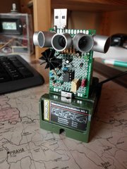 |
184 KB | IR-Sender im Halter, IR-Dioden oben | 1 |
| 09:27, 15. Mai 2014 | IR bake sender unten.JPG (Datei) |  |
165 KB | IR-Sender im Halter, IR-Dioden unten | 1 |
| 09:25, 15. Mai 2014 | IR-bake bauteilseite.JPG (Datei) | 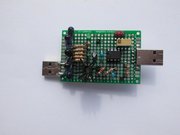 |
126 KB | IR-Sender Bauteilseite | 1 |
| 09:24, 15. Mai 2014 | IR-bake loetseite.JPG (Datei) | 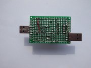 |
158 KB | IR-Sender Lötseite | 1 |
| 09:23, 15. Mai 2014 | IR sender auf steckbrett.jpg (Datei) | 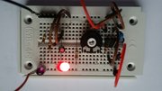 |
108 KB | IR-Sender auf Steckbrett | 1 |
| 07:42, 12. Mai 2014 | Ladestation neben RP6-1.JPG (Datei) | 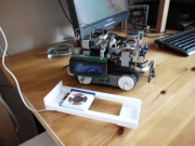 |
75 KB | Ladestation neben RP6 | 1 |
| 16:12, 11. Mai 2014 | Verdrahtung auf RP6-2.JPG (Datei) |  |
121 KB | Verdrahtung der Lade-elektronik am RP6 | 1 |
| 16:11, 11. Mai 2014 | Kabelverlauf.JPG (Datei) | 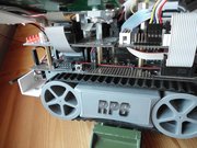 |
222 KB | Kabelverlauf auf der Baseplate | 1 |
| 16:10, 11. Mai 2014 | Gestell von unten.JPG (Datei) | 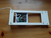 |
134 KB | Ladestation von unten | 1 |
| 16:07, 11. Mai 2014 | Step up converter auf dem steckbrett.JPG (Datei) | 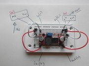 |
169 KB | Step-Up-Converter auf dem Steckbrett | 1 |
| 16:05, 11. Mai 2014 | Step up converter montiert-1.JPG (Datei) | 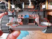 |
197 KB | Step-Up-Converter auf der Bodenwanne montiert | 1 |
| 16:03, 11. Mai 2014 | Step-up-converter.jpg (Datei) | 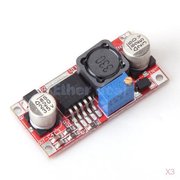 |
33 KB | Step-Up-Converter 4V auf 30V | 1 |
| 16:02, 11. Mai 2014 | SMD-diode auf IN- steckbrett.JPG (Datei) | 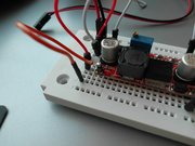 |
186 KB | SMD Diode auf Anschluss IN+ gelötet | 1 |
| 16:00, 11. Mai 2014 | Sekundär spule geklebt.JPG (Datei) | 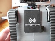 |
263 KB | Sekundärspule an der Bodenwanne geklebt | 1 |
| 15:59, 11. Mai 2014 | Sekundär spule.JPG (Datei) | 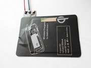 |
235 KB | Sekundärspule mit Anschlussdrähten | 1 |
| 15:58, 11. Mai 2014 | Messungen strom spannung beim laden.png (Datei) |  |
51 KB | Spannungs- und Stromwerte während des Ladens | 1 |
| 15:55, 11. Mai 2014 | USB Stecker pinbelegung.png (Datei) | 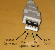 |
117 KB | Pinbelegung USB-Stecker | 1 |
| 15:49, 11. Mai 2014 | IQ ladeschale-1.JPG (Datei) | 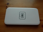 |
149 KB | IQ-Ladestation Kaufteil | 3 |
| 15:47, 11. Mai 2014 | Lichtleitfaser an der elektronik.JPG (Datei) | 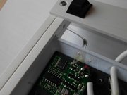 |
230 KB | Lichtleitfaser an der LED der Lade-elektronik | 1 |
| 15:46, 11. Mai 2014 | Ladespule von unten.JPG (Datei) | 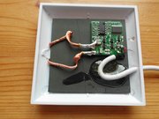 |
157 KB | Primäre Ladespule von unten | 1 |
| 15:45, 11. Mai 2014 | Ladespule kpl.JPG (Datei) | 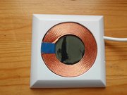 |
138 KB | Primäre Ladespule kpl. | 1 |
| 15:44, 11. Mai 2014 | Gestell von oben.JPG (Datei) | 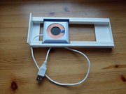 |
166 KB | Ladestation von oben | 1 |
| 13:53, 11. Mai 2014 | Blaue LED als Ladekontrolle.JPG (Datei) | 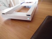 |
249 KB | blaue LED leuchtet, wenn die Ladestation an ist, beim Laden blinkt sie | 1 |
| 13:30, 11. Mai 2014 | Frequenz berechnung IR bake.png (Datei) | 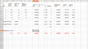 |
74 KB | Tabelle Frequenzberechnung IR-bake | 2 |
| 13:27, 11. Mai 2014 | IQ ladeschale mit ladeelektronik.JPG (Datei) | 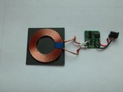 |
118 KB | IQ Ladespule mit Lade-elektronik und Stecker | 2 |
Erste Seite |
Vorherige Seite |
Nächste Seite |
Letzte Seite |
