Inhaltsverzeichnis
- 1 Einleitung
- 2 Text-Displays
- 3 Graphik-Displays
- 4 Siehe auch
- 5 Weblinks
- 6 Autore(en)
Einleitung
LCD ist eine Abkürzung und bedeutet Liquid Crystal Display. Übersetzt bedeutet dies Flüssigkristall-Anzeige. Flüssigkristalle sind organische Verbindungen, die Eigenschaften von Flüssigkeiten und Festkörpern besitzen. Zwischen zwei Glasplatten mit Polarisationsfiltern schwimmen die Flüssigkristalle. Durh Anlegen einer Wechselspannung ändert sich die Polarisationsebene der Flüssigkristalle und damit, ob das einfallende Licht reflektiert oder absorbiert wird.
Bei einem LCD-Modul befindet sich neben dem LCD auch ein Controller zur Ansteuerung des LCDs.
Text-Displays
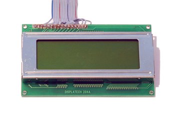
Text-Displays kommen wegen der problemlosen Anbindung in Mikrocontroller Projekten wie Robotern am häufigsten zum Einsatz. Bei Text-LCDs kommen meistens der HD44780 von Hitachi oder ein kompatibler Controller zum Einsatz. Dieser Controller unterstützt Displays mit bis zu 80 Zeichen. Gängige Displaygrößen sind: 8 × 1, 8 × 2, 16 × 1, 16 × 2, 20 × 2, 20 × 4, 40 × 2 Zeichen Displays (Spalten × Zeilen). Hat das Display mehr als 80 Zeichen, dann benötigt das Display 2 Controller und verhält sich nach außen zur Ansteuerung, wie 2 Displays (zusätzliche Enable Leitung)
Anschlußbelegung für ≤80 Zeichen Displays
Text-Displays verfügen über einen über genormte 14 Anschluß Pins (LCD-Module mit Backlight über 16 Pins). Lediglich bei der Backlight Versorgungsspannung und Polung kann es Unterschiede geben. Im Zweifelsfall hilft hier der Blick ins Datenblatt. Entweder sind die Anschlüsse in einer Reihe (1 × 14(16)) oder zweireihig (2 × 7(8)) herausgeführt.
| Pin | Bezeichnung | Beschreibung |
| 1 | GND | Masse |
| 2 | VCC | Spannungsversorgung +5V |
| 3 | VEE | Kontrast Poti 0..0,5V |
| 4 | RS | Register Select, 1=Daten schreiben / 0=Kommando senden. |
| 5 | R/W | 1=Read / 0=Write zum lesen / schreiben in das Display RAM |
| 6 | Enable | Fallende Flanke -> Übertragen des Kommandos oder der Daten, H-Pegel -> Lesen von Daten aus dem Display |
| 7 | DB0 | Datenbus Bit0 LSB |
| 8 | DB1 | Datenbus Bit1 |
| 9 | DB2 | Datenbus Bit2 |
| 10 | DB3 | Datenbus Bit3 |
| 11 | DB4 | Datenbus Bit4 |
| 12 | DB5 | Datenbus Bit5 |
| 13 | DB6 | Datenbus Bit6 |
| 14 | DB7 | Datenbus Bit7 MSB |
HD44780 kompatibler LCD Controller
Der HD44780 LCD Controller besitzt 3 Speicher. Den DDRAM (Display Data RAM) Darin werden die anzuzeigenden Daten geschrieben. Der CGROM (Character Generator ROM) enthält die Zeichen in Form von 5x8 oder 5x10 Punktmatrizen. Im CGRAM (Character Generator RAM) können acht benutzerdefinierte Zeichen 5x8 Pixel oder vier 5x10 Pixel abgelegt werden.
Befehlsübersicht
| Befehl | RS | R/W | DB7 | DB6 | DB5 | DB4 | DB3 | DB2 | DB1 | DB0 | Beschreibung | Ausführungszeit bei fosc=250kHz |
| Clear Display | 0 | 0 | 0 | 0 | 0 | 0 | 0 | 0 | 0 | 1 | Löscht das Display und setzt den Cursor auf den Anfang der 1. Zeile (Addresse 0). | 1.64mS |
| Cursor Home | 0 | 0 | 0 | 0 | 0 | 0 | 0 | 0 | 1 | * | setzt den Cursor auf das Anfang der 1. Zeile (Addresse 0) | 1.64mS |
| Entry mode set | 0 | 0 | 0 | 0 | 0 | 0 | 0 | 1 | I/D | S | Setzt die Cursor Bewegungsrichtung (I/D), spezifiziert das Display zu schieben (S). Diese Operationen werden während des Daten lesen/schreiben durchgeführt. | 40uS |
| Display on/off Control | 0 | 0 | 0 | 0 | 0 | 0 | 1 | D | C | B | Schaltet an/aus: das gesamte Display (D), Den Cursor (C) Cursor blinken (B). | 40uS |
| Cursor/Display shift | 0 | 0 | 0 | 0 | 0 | 1 | S/C | R/L | * | * | Setzt Cursor Bewegung oder Display Bewegung (S/C), Bewegungsrichtung (R/L) | 40uS |
| Function set | 0 | 0 | 0 | 0 | 1 | DL | N | F | * | * | Einstellen der Schnittstellen Datenlänge (DL), Anzahl Display Zeilen (N) und Zeichen Font (F). | 40uS |
| Set CGRAM Address | 0 | 0 | 0 | 1 | CGRAM Adresse | Setzen der CGRAM Adresse. CGRAM Daten werden gesendet und empfangen nach dem setzen. | 40uS | |||||
| Set DDRAM Address | 0 | 0 | 1 | DDRAM Adresse | Setzen der DDRAM Adresse. DDRAM Daten werden gesendet und empfangen nach dem setzen. | 40uS | ||||||
| Read busy-flag and address counter | 0 | 1 | BF | CGRAM / DDRAM Adresse | Liest das Busy-flag (BF), welches anzeigt das interne Operationen ausgeführt werden, und liest den CGRAM oder DDRAM Adress Zeiger Inhalt. | 0uS | ||||||
| Write to CGRAM or DDRAM | 1 | 0 | Schreib Daten | Schreibt Daten zum CGRAM oder DDRAM. | 40uS | |||||||
| read from CGRAM or DDRAM | 1 | 1 | Lese Daten | Liest Daten vom CGRAM oder DDRAM. | 40uS | |||||||
Anmerkungen:
- DDRAM = Display Data RAM.
- CGRAM = Character Generator RAM.
- DDRAM Adresse entspricht der Cursor Position.
- * = egal.
| Bit Name | Einstellung / Status | |
| I/D | 0 = Erniedrige Cursor Position | 1 = Erhöhe Cursor Position |
| S | 0 = Display nicht shieben | 1 = Display schieben |
| D | 0 = Display aus | 1 = Display an |
| C | 0 = Cursor aus | 1 = Cursor an |
| B | 0 = Cursor blinken aus | 1 = Cursor blinken an |
| S/C | 0 = Bewege Cursor | 1 = Schiebe Display |
| R/L | 0 = Schiebe nach links | 1 = Schiebe nach rechts |
| DL | 0 = 4-bit Interface | 1 = 8-bit Interface |
| N | 0 = 1/8 oder 1/11 Duty (1 Zeile) | 1 = 1/16 Duty (2 Zeilen) |
| F | 0 = 5x7 Punkte | 1 = 5x10 Punkte |
| BF | 0 = Befehle werden akzeptiert | 1 = Interne Operation wird ausgeführt |
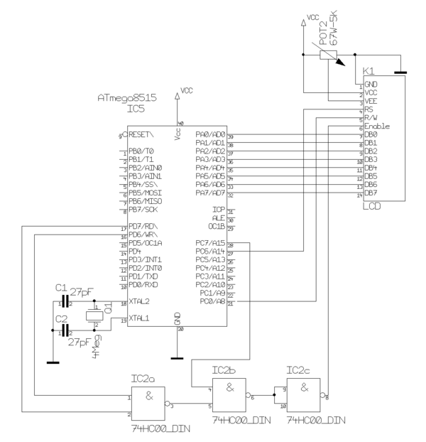
8-Bit Ansteuerung (Busmode)
Für die 8-Bit Busmode Ansteuerung funktioniert nur bei AVR Prozessoren mit externem Bus Interface. Diesen Mode unterstützen allerdings nur die wenigsten Atmel AVR Prozessoren, z.B. der AT90S8515 und ATmega128. Der Busmode empfiehlt sich, wenn man in der Applikation auch externen Speicher verwendet.
BASCOM-AVR Programm
Das Programm zur Ansteuerung des Displays im 8-Bit Bus Mode.
 $regfile = "8515def.dat"
 $crystal = 4000000
 $lcd = &HC000       'Adresse LCD Daten
 $lcdrs = &H8000     'Adresse LCD Register select

 Config Lcdbus = 8   'LCD im 8-Bit Bus Mode
 Config Lcd = 16 * 2 'wir verwenden ein 16 x 2 Zeichen Display

 Cls                 'loesche das LCD Display
 Locate 1 , 1        'Cursor auf 1 Zeile, 1 Spalte
 Lcd "Hello world."  'String auf Display anzeigen

 ...
AVR-GCC Programm
Das Programm zur Ansteuerung des Displays im 8-Bit Bus Mode. Verwendet wird die lcdlibrary von Peter Fleury.
Folgende Einstellungen sind für obiges Beispile in der Header Datei lcd.h vorzunehmen:
/**
 *  @name  Definitions for MCU Clock Frequency
 *  Adapt the MCU clock frequency in Hz to your target.
 */
#define XTAL 4000000              /**< clock frequency in Hz, used to calculate delay timer */


/**
 * @name  Definition for LCD controller type
 * Use 0 for HD44780 controller, change to 1 for displays with KS0073 controller.
 */
#define LCD_CONTROLLER_KS0073 0  /**< Use 0 for HD44780 controller, 1 for KS0073 controller */

/**
 *  @name  Definitions for Display Size
 *  Change these definitions to adapt setting to your display
 */
#define LCD_LINES           2     /**< number of visible lines of the display */
#define LCD_DISP_LENGTH    16     /**< visibles characters per line of the display */
#define LCD_LINE_LENGTH  0x40     /**< internal line length of the display    */
#define LCD_START_LINE1  0x00     /**< DDRAM address of first char of line 1 */
#define LCD_START_LINE2  0x40     /**< DDRAM address of first char of line 2 */
#define LCD_START_LINE3  0x14     /**< DDRAM address of first char of line 3 */
#define LCD_START_LINE4  0x54     /**< DDRAM address of first char of line 4 */
#define LCD_WRAP_LINES      0     /**< 0: no wrap, 1: wrap at end of visibile line */

#define LCD_IO_MODE      0         /**< 0: memory mapped mode, 1: IO port mode */
#if LCD_IO_MODE
/**
 *  @name Definitions for 4-bit IO mode
 *  Change LCD_PORT if you want to use a different port for the LCD pins.
 *
 *  The four LCD data lines and the three control lines RS, RW, E can be on the
 *  same port or on different ports.
 *  Change LCD_RS_PORT, LCD_RW_PORT, LCD_E_PORT if you want the control lines on
 *  different ports.
 *
 *  Normally the four data lines should be mapped to bit 0..3 on one port, but it
 *  is possible to connect these data lines in different order or even on different
 *  ports by adapting the LCD_DATAx_PORT and LCD_DATAx_PIN definitions.
 *
 */
#define LCD_PORT         PORTA        /**< port for the LCD lines   */
#define LCD_DATA0_PORT   LCD_PORT     /**< port for 4bit data bit 0 */
#define LCD_DATA1_PORT   LCD_PORT     /**< port for 4bit data bit 1 */
#define LCD_DATA2_PORT   LCD_PORT     /**< port for 4bit data bit 2 */
#define LCD_DATA3_PORT   LCD_PORT     /**< port for 4bit data bit 3 */
#define LCD_DATA0_PIN    0            /**< pin for 4bit data bit 0  */
#define LCD_DATA1_PIN    1            /**< pin for 4bit data bit 1  */
#define LCD_DATA2_PIN    2            /**< pin for 4bit data bit 2  */
#define LCD_DATA3_PIN    3            /**< pin for 4bit data bit 3  */
#define LCD_RS_PORT      LCD_PORT     /**< port for RS line         */
#define LCD_RS_PIN       4            /**< pin  for RS line         */
#define LCD_RW_PORT      LCD_PORT     /**< port for RW line         */
#define LCD_RW_PIN       5            /**< pin  for RW line         */
#define LCD_E_PORT       LCD_PORT     /**< port for Enable line     */
#define LCD_E_PIN        6            /**< pin  for Enable line     */

#elif defined(__AVR_AT90S4414__) || defined(__AVR_AT90S8515__) || defined(__AVR_ATmega64__) || \
      defined(__AVR_ATmega8515__)|| defined(__AVR_ATmega103__) || defined(__AVR_ATmega128__) || \
      defined(__AVR_ATmega161__) || defined(__AVR_ATmega162__)
/*
 *  memory mapped mode is only supported when the device has an external data memory interface
 */
#define LCD_IO_DATA      0xC000    /* A15=E=1, A14=RS=1                 */
#define LCD_IO_FUNCTION  0x8000    /* A15=E=1, A14=RS=0                 */
#define LCD_IO_READ      0x0100    /* A8 =R/W=1 (R/W: 1=Read, 0=Write   */
#else
#error "external data memory interface not available for this device, use 4-bit IO port mode"

#endif
So sieht das Programmbeispiel in AVR-GCC aus:
#include <stdlib.h>
#include <avr/io.h>
#include "lcd.h"

int main(void)
{

    /* Initialisiere Display, Cursor aus */
    lcd_init(LCD_DISP_ON);

    /* loesche das LCD Display und Cursor auf 1 Zeile, 1 Spalte */
    lcd_clrscr();

    /* String auf Display anzeigen */
    lcd_puts("Hello world.");

    ...
4-Bit Ansteuerung (I/O Mode)
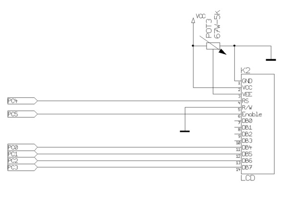
Mit die häufigste Anbindungsart ist sicher die 4-Bit Ansteuerung. Dabei werden die Display-Daten Nibble-weise in den Display Speicher übertragen. Das ist zwar etwas langsamer als im 8-Bit Mode, das spielt aber kaum eine Rolle. Für diese Ansteuerung werden 6 Prozessor Ports benötigt. Die R/W Leitung des Displays kann man dabei einfach auf GND legen, dann ist aber keine Busy-Bit Abfrage möglich.
BASCOM-AVR Programm
Das Programm zur Ansteuerung des Displays im 4-Bit I/O Mode.
 $regfile = "m32def.dat"
 $crystal = 16000000

 Config Lcd = 20 * 4   'wir verwenden ein 4 x 20 Zeichen Display
 ' Im I/O Mode wird jeder Prozessor Pin einzeln angegeben
 Config Lcdpin = Pin , Db4 = Portc.0 , Db5 = Portc.1 , Db6 = Portc.2 , Db7 = Portc.3 , E = Portc.5 , Rs = Portc.4

 Cls                   'loesche das LCD Display
 Locate 1 , 1          'Cursor auf 1 Zeile, 1 Spalte
 Lcd "Hello world."    'String auf Display anzeigen

 ...
AVR-GCC Programm
Das Programm zur Ansteuerung des Displays im 4-Bit I/O Mode. Verwendet wird die lcdlibrary von Peter Fleury.
Folgende Einstellungen sind für obiges Beispile in der Header Datei lcd.h vorzunehmen:
/**
 *  @name  Definitions for MCU Clock Frequency
 *  Adapt the MCU clock frequency in Hz to your target.
 */
#define XTAL 16000000              /**< clock frequency in Hz, used to calculate delay timer */


/**
 * @name  Definition for LCD controller type
 * Use 0 for HD44780 controller, change to 1 for displays with KS0073 controller.
 */
#define LCD_CONTROLLER_KS0073 0  /**< Use 0 for HD44780 controller, 1 for KS0073 controller */

/**
 *  @name  Definitions for Display Size
 *  Change these definitions to adapt setting to your display
 */
#define LCD_LINES           4     /**< number of visible lines of the display */
#define LCD_DISP_LENGTH    20     /**< visibles characters per line of the display */
#define LCD_LINE_LENGTH  0x40     /**< internal line length of the display    */
#define LCD_START_LINE1  0x00     /**< DDRAM address of first char of line 1 */
#define LCD_START_LINE2  0x40     /**< DDRAM address of first char of line 2 */
#define LCD_START_LINE3  0x14     /**< DDRAM address of first char of line 3 */
#define LCD_START_LINE4  0x54     /**< DDRAM address of first char of line 4 */
#define LCD_WRAP_LINES      0     /**< 0: no wrap, 1: wrap at end of visibile line */

#define LCD_IO_MODE      1         /**< 0: memory mapped mode, 1: IO port mode */
#if LCD_IO_MODE
/**
 *  @name Definitions for 4-bit IO mode
 *  Change LCD_PORT if you want to use a different port for the LCD pins.
 *
 *  The four LCD data lines and the three control lines RS, RW, E can be on the
 *  same port or on different ports.
 *  Change LCD_RS_PORT, LCD_RW_PORT, LCD_E_PORT if you want the control lines on
 *  different ports.
 *
 *  Normally the four data lines should be mapped to bit 0..3 on one port, but it
 *  is possible to connect these data lines in different order or even on different
 *  ports by adapting the LCD_DATAx_PORT and LCD_DATAx_PIN definitions.
 *
 */
#define LCD_PORT         PORTC        /**< port for the LCD lines   */
#define LCD_DATA0_PORT   LCD_PORT     /**< port for 4bit data bit 0 */
#define LCD_DATA1_PORT   LCD_PORT     /**< port for 4bit data bit 1 */
#define LCD_DATA2_PORT   LCD_PORT     /**< port for 4bit data bit 2 */
#define LCD_DATA3_PORT   LCD_PORT     /**< port for 4bit data bit 3 */
#define LCD_DATA0_PIN    0            /**< pin for 4bit data bit 0  */
#define LCD_DATA1_PIN    1            /**< pin for 4bit data bit 1  */
#define LCD_DATA2_PIN    2            /**< pin for 4bit data bit 2  */
#define LCD_DATA3_PIN    3            /**< pin for 4bit data bit 3  */
#define LCD_RS_PORT      LCD_PORT     /**< port for RS line         */
#define LCD_RS_PIN       4            /**< pin  for RS line         */
#define LCD_RW_PORT      LCD_PORT     /**< port for RW line         */
#define LCD_RW_PIN       6            /**< pin  for RW line         */
#define LCD_E_PORT       LCD_PORT     /**< port for Enable line     */
#define LCD_E_PIN        5            /**< pin  for Enable line     */

#elif defined(__AVR_AT90S4414__) || defined(__AVR_AT90S8515__) || defined(__AVR_ATmega64__) || \
      defined(__AVR_ATmega8515__)|| defined(__AVR_ATmega103__) || defined(__AVR_ATmega128__) || \
      defined(__AVR_ATmega161__) || defined(__AVR_ATmega162__)
/*
 *  memory mapped mode is only supported when the device has an external data memory interface
 */
#define LCD_IO_DATA      0xC000    /* A15=E=1, A14=RS=1                 */
#define LCD_IO_FUNCTION  0x8000    /* A15=E=1, A14=RS=0                 */
#define LCD_IO_READ      0x0100    /* A8 =R/W=1 (R/W: 1=Read, 0=Write   */
#else
#error "external data memory interface not available for this device, use 4-bit IO port mode"

#endif
So sieht das Programmbeispiel in AVR-GCC aus:
#include <stdlib.h>
#include <avr/io.h>
#include "lcd.h"

int main(void)
{

    /* Initialisiere Display, Cursor aus */
    lcd_init(LCD_DISP_ON);

    /* loesche das LCD Display und Cursor auf 1 Zeile, 1 Spalte */
    lcd_clrscr();

    /* String auf Display anzeigen */
    lcd_puts("Hello world.");

    ...
Ansteuerung über Porterweiterung
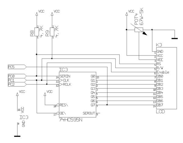
Mit einem Porterweiterungs Baustein wie dem 74HC595 lassen sich weitere Prozessor-Ports einsparen. Diese Lösung kommt mit 4 Prozessor Ports aus, läßt man die Abfrage des Busy-Bits (PC5) weg, sogar nur mit 3 Prozessor Ports. Trotzdem wird das Display im 8-Bit Mode betrieben.
BASCOM-AVR Programm
Das BASCOM Programm für diese Ansteuerung ist nicht ganz so einfach, da es nicht von der BASCOM Library unterstützt wird. Die Routinen zum Ansprechen des Displays muß man selbst coden.
TODO....
AVR-GCC Programm
TODO....
Ansteuerung über I²C
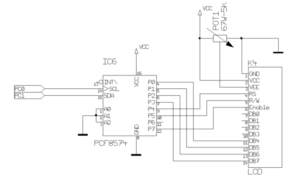
Nur 2 Prozessor Ports benötigt man bei der I²C-Ansteuerung. Dazu wird als I²C Porterweiterungs IC der PCF8574P benötigt.
BASCOM-AVR Programm
Diese Ansteuerung basiert auf der Application Note AN#118 von MCS electronics. Dazu gibt es auch eine fertige Library zu BASCOM-AVR, die die Standard LCD Library ersetzt. Dadurch können die gleichen Befehle zur Ansteuerung verwendet werden wie bei der Standard LCD Library. Das BASCOM-AVR Programm, um das LCD-Modul über I²C anzusprechen, sieht dann so aus.
 $lib "Lcd_i2c.lib"   'ersetzt die Standard LCD Library
 $regfile = "m32def.dat"
 $crystal = 16000000

 Const Pcf8574_lcd = &H40   'I2C Adresse
 Config Scl = Portc.0       'I2C SCL Pin
 Config Sda = Portc.1       'I2C SDA Pin
 Dim _lcd_e As Byte
 _lcd_e = 128               'LCDim 4-Bit Mode betreiben

 Cls                'loesche das LCD Display
 Locate 1 , 1       'Cursor auf 1 Zeile, 1 Spalte
 Lcd "Hello world." 'String auf Display anzeigen

 ...
AVR-GCC Programm
TODO....
Ansteuerung über RS232
Ebenfalls nur 2 Pins zur Ansteuerung benötigt die Lösung. Allerdings ist die serielle Schnittstelle bei Mikrocontrollern oft schon mit anderen Aufgaben belegt. Deshalb befindet sich meistens noch zusätzlich eine I²C-Bus Schnittstelle zur Ansteuerung auf dem Modul.
Graphik-Displays
In Mikrocontroller Anwendungen seltener anzutreffen sind Grafik-Displays. Da der Aufwand hier um einiges höher ist (jeder Pixel ist einzeln anzusteuern), kommen in der Praxis nur Grafik-Displays mit RS232 oder I²C-Bus Ansteuerung zum Einsatz.
Siehe auch
Weblinks
- MCS electronics AN #118 - I²C LCD and Keyboard library
- Peter Fleury's Homepage - Interfacing a HD44780 Based LCD to an AVR, LCD library for HD44870 based LCD's
Autore(en)

